


A disused railway station below half of a central London site meant conventional piling was out of the question. The team that built a five-storey basement under Claridge’s hotel while keeping it open were drafted in to come up with a radical solution
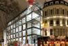
Ground engineering is not usually a candidate for TV drama, but two years ago the extraordinary story of how Claridge’s hotel built the ultimate iceberg basement under its 100-year-old building while remaining open for guests made it onto the small screen. A BBC TV crew spent six years filming the construction of a five-storey basement for a swimming pool, spa and back of house facilities.
To build the basement without disturbing the hotel was essentially a mining job. Small tunnels and shafts up to 30m deep were hand-dug under the building’s raft foundation and 62 existing columns. New concrete piles were built in the shafts to support the building above, then the rest of the basement could be excavated for fitting out.
Now the former Claridge’s team of specialist contractor McGee and geotechnical engineer RKD Consultant have come together to pioneer a radical new piling technique in a bid to extract as much value out of a particularly difficult development site in central London.
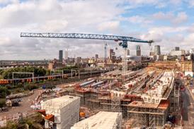
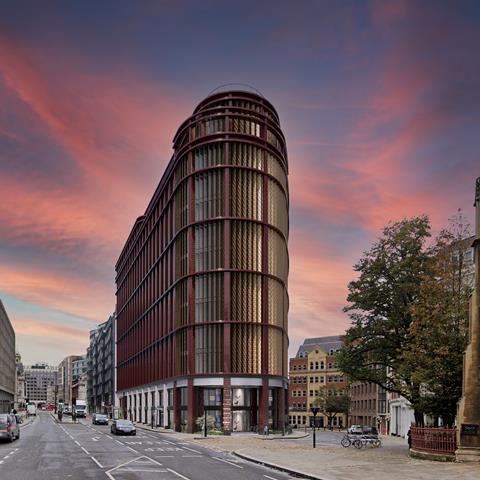
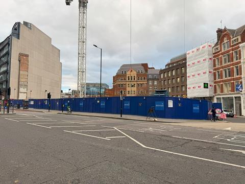
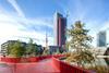
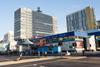
Located on the junction of Holborn Viaduct and Snow Hill, developer Dominus is building a 669-bed, 12-storey student accommodation block. Half the site sits over the abandoned Snow Hill station between City Thameslink and Farringdon stations on the Thameslink line running through central London.
The previous building on the site was constructed in the 1960s at a time when the railway line was not operational, so piling the foundations through the station was relatively straightforward. This option was not open to Dominus as the line reopened in 1988, making the work disruptive and potentially damaging to the railway. And the precast plank roof of the tunnel, which was installed as part of the construction of the 1960s building, could not take the weight of a piling rig.
“It was quite complicated and constrained and almost impossible to build this building using traditional construction methods,” explains Anupriya Rajpal, the development director at Dominus responsible for the project.
The original plan had been to build a hotel on the site, but the pandemic devastated the hospitality market and a severe, local shortage of student accommodation prompted a change of use. Rajpal says the initial idea was to support the part of the hotel over the railway with a huge, 30m-long cantilever, but the railway is just one of multiple underground infrastructure elements constraining the site.
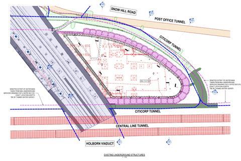
The Central line runs under Holborn Viaduct just metres from the site on the south side and there is a redundant Post Office railway tunnel to the north. The site is also ringed by City of London service subways housing electrical and data cabling. And old viaducts retaining the pavement ring the part of the site away from the railway line.
“A cantilever that long has never been done in the UK, so there was no precedent, which would have been a concern for the stakeholders with assets surrounding the project,” Rajpal explains. “Because of the viaducts and city subway tunnels, there is a restriction on the loads that can be brought to site.
“A cantilever would have meant mega-trusses being brought down to the site almost every other week for connection on site, but that would have been difficult because of the tunnels and the viaducts. We would have had to come up with a solution using smaller pieces of steel. This would have made the trusses problematic because of stakeholder engagement and approvals.”
The pandemic imposed a pause on the project which gave the team time to think again. Borrowing from their experience at Claridge’s, Lem Berihun, who was a senior project manager at McGee but has since moved over to Dominus in the same role, and Adam Pellew, a director of RKD Consultant, came up with a novel solution that would have minimal impact on Network Rail’s assets and could be done while the trains were running.
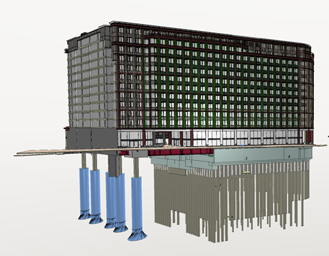
Like Claridge’s, this solution involved hand-digging. Five caisson piles, so called because of their size and function, will be installed in a line some 5m apart along the railway platform closest to the west boundary of the site. Steel trusses will bridge over the railway line to the conventional foundation on the east side of the site and support the building above.
Each pile is approximately 20m deep and 1.8m in diameter at platform level. This bells out to 2.7m halfway down and out again to 4m diameter towards the base. The last 1.2m section expands out to 5.5m at the base of the pile.
“The whole game is to get a nice big area on the base,” explains Pellew. “The whole thing is a big footing, really.” Each pile can take a load of 15 to 17 mega newtons.

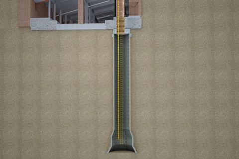
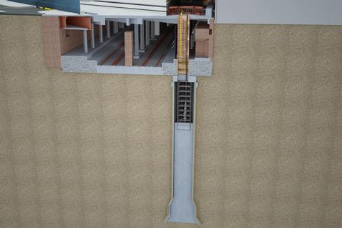

Diagrammatic sequence showing the theory behind the caisson piles construction. Please note that the diagrams are indicative only
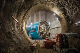
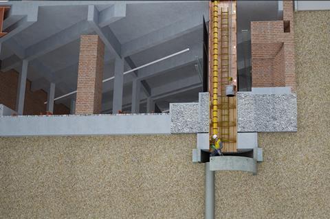
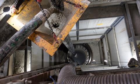
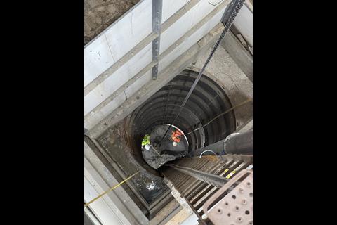
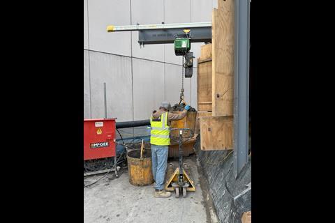
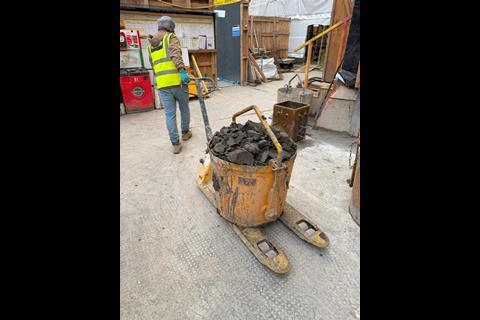
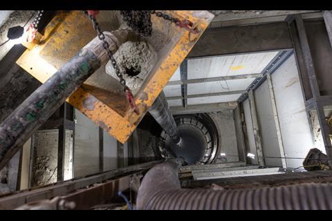
The excavation technique could not be more basic. Two workers armed with shovels dig out the London clay into a bucket, which is then hauled out of the hole using a rope and pulley. The spoil is deposited onto a conveyor and the bucket lowered ready for the next load.
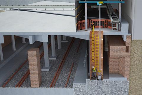
A fixed ladder provides access into the pile and fresh air is blown down a pipe to the base. Before digging starts, a rectangular, fireproof enclosure is built between the station platform and tunnel roof during engineering hours so the work can continue during the day when trains are running. A hole is cut in the tunnel roof for access to the enclosure and ground below.
As the workers dig down, steel segments are inserted into the pile every 2.5m to retain the sides. These segments feature studs on the back which engage with the grout that is pumped into the gap between the segment and clay behind. This stops the segments dropping down where the pile bells out.
Concrete segments are used where the pile extends to 2.7m diameter and below. Once the base has been reached, and the dome dug out, mass concrete is pumped into the pile until approximately the halfway point, with steel reinforcement for the upper half. A precast column is used for the section in the tunnel – once this has been installed the enclosure can be removed.
According to Pellew, one major consideration was vibration from the trains affecting the residents in the building above. This is taken care of by large rubber bearings between the concrete columns and steel structure above on both sides of the building. A piled raft was selected for the east side of the building because this would settle at the same rate as the caisson piles.
“I was trying to keep the movements reasonably similar so that both sets of bearings were operating within their loading windows,” Pellew explains. “That was a key element of the foundation design philosophy that we grappled with.”
Getting to the point where work could start on the caisson piles took years of planning and negotiation with Network Rail and other stakeholders with assets near the project.
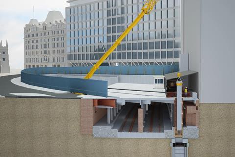
Sequence showing the caisson piles under construction
Berihun says the biggest challenge was mapping out the locations of the caisson piles and columns to support the superstructure above with minimal disruption to existing infrastructure. The challenge was the historical accretion of old structures and Network Rail infrastructure between the superstructure and the pile.
There were three main elements to negotiate around: the primary beams supporting the tunnel roof, Network Rail signal cabling on the platforms and the piles and pile caps of the building that formerly occupied the site.
Pellew says the cabling laid over the platforms was problematic as there was so much of it. “There was no need for Network Rail to take out redundant services when these were upgraded. Over the years, they have just bolted on more and more. So our challenge was figuring out what was redundant. And it is the nature of Network Rail that there were no as-built drawings available, so we had to do it on visual surveys.”
Locating the old piles and pile caps was even more challenging as these were hidden below ground, necessitating intrusive surveys. These had to be carried out at night outside railway operating hours.
“We had to dig down about three metres from platform level to find the existing piles,” Berihun says. “We only had a window of time to do that before the railway opened again in the morning, and we had to leave a few hours before that so Network Rail could certify the area as safe every time.”
He adds that the excavations had to be filled in before the lines reopened regardless of whether the survey had been completed. “It took a long time to get all the information that we needed for the five different locations.”
It took two and a half years to find the best fit for the piles and obtain all the necessary permits. All the caissons were dug from ground level thanks to Network Rail moving some of the cabling and getting permission to cut through some of the structure supporting the tunnel.
Given the challenges presented by the maze of underground tunnels in London, could this technique be used to unlock other sites? Rajpal says the redundant platforms at Snow Hill meant there was plenty of room to accommodate the work and new structure which would not be the case for London Underground or other similar-sized tunnels. But piles can be installed reasonably close to these and the width from one side to the other is easily bridged.
The technique is more likely to be useful for building over large underground facilities like Snow Hill. Rajpal concludes: “As long as the stakeholders and asset owners are comfortable with this methodology, this could be quite groundbreaking in terms of how we utilise those tunnels underneath by collaborating with those asset owners to develop their space.”
Project team
Developer Dominus
Architect Stiff + Trevillion
Executive architect TP Bennett
Cost consultant Gardiner &Theobald
Planning consultant DP9
Structural and civil engineering Meinhardt
Network Rail engineer Robert Bird Group
Network Rail design review Aecom
Network Rail tunnel monitoring Plowman Craven
Temporary works design RKD
Main contractor for basement McGee
Main contractor for superstructure McAleer & Rushe


No comments yet